Monday, 28 August 2017

Electronic distributor

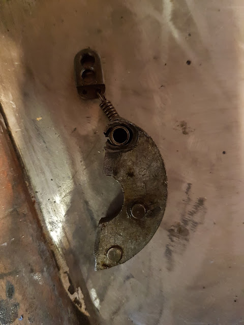
I decided to address the power issue on my Austin Seven, it does not have much but I suspected the distributor was responsible as the higher rev's the power was erratic.  I decided to look at the Lucas distributor. I took off the top plate to find one of the weight pivots was destroyed and effectively had no or at best random mechanical advance.


The simple answer I thought was a new electronic distributor. Asking around the paddock at various hill climb meetings I got mixed reviews of such a change. Some said it was good and others said they reverted to the old one with points because of timing/starting issues.

I decided to buy one at the Austin Seven Guildtown Rally (as it was on offer) and had it fitted at the show. I went on a run with the device but I was plagued with misfires and lack of power at higher revs. The dealer offered to change the unit and in fact he tried another unit which had exactly the same charicteristics. I was  fairly convinced it was due to the application in my car as numerous others had complete success, so I decided to purchase the unit on approval.
It is a nice looking part, I have taken it apart looking for the source of my problems and it all looks well designed and put together. I even tried using similar  advance springs to my original unit.  I put an Oscilloscope on the feed to the coil but I could not discern any abnormal behaviour in the waveforms. The Timing light when connected to the engine when running shows a random timing mark unsteady at any speed. The tick-over is rough. There is no appreciable mechanical slack in the drive to the distributor.

I had a eureka moment after competing at Forrestburn recently and decided the unit may be sensitive to noise from the generator/regulator. I have had problems in the past trying to put electronics in a car due to noise issues. In fact I had the same problem with my cooling pump timer. I decided to make a filter with a few bits lying about in my spares box. The theoretical cut-off frequency of the filter of this type is 1/(2*PI* SQRT(L*C)) in this case about 1.5KHz. It has a toroidal coil capable of 5A. The capacitor is an 12V electrolytic type so don't get it around the wrong way.


This completely cured the problems. These bits are readily available on either ebay or RS components.
Before potting it in Silkoflex
My times on a hill climb can only improve. See you at Bo'ness revival.


Here is an Index page for the build


Monday, 14 August 2017

Brakes binding

Despite rebuilding the brakes from scratch the brakes are not that good and they have a annoying habit of binding. This can be dangerous on the road when wet as you suddenly go into a skid as one corner bites when they others are still free.

I originally made a jig for truing up the drums on the lathe unfortunately I made a schoolboy error when turning it and I managed to insert a runoff. This was due the fact I was having trouble machining it so I put the backplane blank on backwards to machine it. Transferring it around  frontwards introduced a runoff error. This inserted effectively an offset into the drum when trying to tru them up. The error was only a few thou but magnified by the drum diameters caused a real problem

I discovered the error modified the jig and retried the drums on the car. This has stopped the binding issue now completely.


Lathe jig without runoff error

Here is an Index page for the build


Thursday, 27 July 2017

Accesory power

One consequence of fitting my tool storage is the pump needs 12V power. There is no room to fit a stirrup pump so power is needed. I had no intention of fitting a 12V cigar lighter socket in the middle of the dash so I concealed it under the dash (mostly).


Here is an Index page for the build

Wednesday, 26 July 2017

Tool storage

I am going to a car show soon where they have organised a road run. I thought I had better create a tool storage area for a few spanners and the like just in case! There is no possibility of storage within the cockpit so I guess it will have to be the engine compartment. There is dead space above the passenger foot well, but the tools need to be constrained in some sort of box.

The idea I came up with uses the bonnet as a lid thus doing away with any cover for the box.


Cardboard model
Final fabrication
It is more than enough space for two tool rolls, a jack, electric pump and a torch.

Here is an Index page for the build


Friday, 14 July 2017

Starting issues

The Austin had an original  6V starter and a 12V low capacity race battery installed (to save weight). The problem with this setup is it presents the battery with an abnormally heavy load on starting especially when cold. The result is the engine frequently fails to start even on a fully charged battery  The problem at car  trial  events is there is a lot of stop starting and this rapidly canes the battery as you don't get enough charge on a run to replace the starting power lost.

I had a look at various starters but could not find a conventional 12V starter form another car that would fit  without modification. However there is a company called Powerlite that make a AUSTIN 7 1933-onwards BRAND NEW POWERLITE HIGH TORQUE UPGRADE STARTER MOTOR costing a little under £200 from a company called aapoldham on ebay. I have just fitted the upgrade and I am hopeful this is going to resolve some of the problems. It need less power to crank the engine at a far higher speed and is fully compatible with my 12V  race battery. The ultimate solution would be the addition of a generator/alternator conversion but nobody makes one yet. I live in hope. I found a nice starter button on CBS that looks vintage.


Fits seamlessly to the bell housing.

Plenty of room all round.


Vintage start button

Road test

I took it on a road test a total of 18 miles round trip. The car behaved very well on the trip back but I had to stop and fault find a problem with the ignition. A wire to the distributor LT points connection had come loose. After resolving that that the car behaved faultlessly. I managed an indicated 50mph at 3500 rpm. The addition of the high torque starter has transformed the driving experience and ownership. It now starts the car with no drama and hopefully charges the battery between use. I still have reservations about the use in car trials where a lot of stop starting is involved but the car is now very usable.

Here is an Index page for the build


Saturday, 24 June 2017

Battery charging revisited

I took it for a run today after my local car club gathering in the centre of town. To my discomfort I detected a burning smell under the bulkhead (this side of the fire wall).

The wiring harness was installed some time ago along with a 12V (Lucas 3182) regulator feeding the generator. This has the effect of converting the charging circuit to 12V with only one extra part. The only thing you need in addition to the regulator is a 3 ohm resistor to reduce the field coil current to approx. 2A maximum. In reality I found that to get a reasonable rev point where the charging light went out I had to fit a 2.2 ohm resistor. See: http://austin7special.blogspot.co.uk/2016/02/wiring-harness.html (regulator to field coil designated -F).

This probably means it is dissipating in the region of 16W. I had selected a 20W resistor which was 2 x 10 watt jobs glued on to a fiberglass board with epoxy and mounted on the bulkhead. The resistor rating was ok but the heat from the resistor created a foul smell when driving about due to the epoxy being over heated.

Old arrangement
I decided to change the arangement by mounting a single aluminium clad 50W resistor onto an extruded aluminium heat sink and bolted it on it's original location under the dash. This is complete over designed solution for what it is......but I wanted this problem to go away as I hate the smell of burning glue.

I had a standard alloy heat sink extrusion laying about from another project so I machined a lump out of the middle to take the resistor and it's M4 fixings, precision drilled 2 more holes to mount it (where it had been before) and machined some plastic insulators to terminate the wiring connectors (M5 tags either end of the resistor) and secured them in place with rivnuts.

The charging ability of my setup is not great but is now somewhat more reliable and more pleasant to drive with. All I need now is some dry weather to try it out!

New alloy extrusion solution

Update 4th Aug 21

The generator has been replaced by an Alternator, no mre charging issues.


Here is an Index page for the build


Friday, 5 May 2017

Lights

Front

I was not going to add lights as it is mainly going to be used for car trials. However running it on the road would give me the advantage of testing for reliability outside track days. I feel I need road legal lights. I did a 12V conversion on the generator/regulator and I am using a race battery with limited capacity so I converted all the lights to LED. The battery will not take a charge till above tick over and there is a lot of tick over/starting at car trials. The headlights are 1938 pattern "King of the road" Lucas 4 1/2" headlights. There is no way the generator will support conventional 2 x 35W headlamp bulbs, so I sourced a 2 x high power sop/ tail LED bulbs. The low power (tail) acts as dip and side lights and the high power (stop) gives me main beam.

The indicator pods had 21W bulbs but now have 2W high intensity LED conversions.


Rear

The rear was a little more tricky to fabricate, but a lump of cardboard, a box bender, and a little welding att the corners produced the necessary assembly to hold the number plate and lights. The light units are LED indicator + Stop/Side variety are from a vintage motorcycle dealer on ebay. The number plate light was fabricated with a right angle fabrication and a 300mm waterproof LED strip from ebay.


Brake lights

I had a tad of a problem getting the brake lights working despite having all the original hardware so I thought the following worth mentioning. The brake light switch did not align with the tab on the actuating rod. This adverse angle resulted in stiction being applied the switch assembly resulting in the lights staying on after applying the brakes (hysteresis). I had to make an extension to the attachment tab to ensure alignment (and therefore minimising the stiction). I also found the spring tension was critical, I used a brake shoe spring.

Summary

I now have a viable lighting setup that will not flatten the battery while ticking over. All side lights (4) take 0.33A or 4W and the side + headlights 1.5A or 18W total. This compares with incandescent lamps which take 20W and 70W respectively.

Update 4th Aug 21

The major change was a) Fitting an alternator b) The headlights have been upgraded with Vespa inserts to comply with the MoT requirements.

Here is an Index page for the build

Friday, 14 April 2017

Testing at Forrestburn

List of development issues this year

The Monklands Sporting Car Club (MSCC), my local car club have an early season event called a Car Trial. I used this to test out my winter modifications. The car is still in it's early stages so needs to be proved and what better way than to enter it into a car trial.

1) Gear Change:- After adjusting it correctly, the clutch is definitely fixed, no dragging issues any more. The gear change 1-2nd is clunky no synchro but I suspect that is normal..

2) Battery drain:- This eventually made me give up the last event see: battery-drain-problems. The electronic timer modulator on the water pump is working a treat. I put it in a sealed box now and wired it in permanently (out of sight) it comes on with the ignition now (in case I forget). No overheating problems despite a 80% off 20% ON. The timer box can be removed quickly if necessary. I will order a spare battery however as the frequent stop starting on an event will still drain the battery down. It will last till lunch time then change it over if necessary.

3) Fluid Leaks:- The latest water leak from the engine is now fixed, a friend  helped me remove the side alloy casting, trued it up on the belt sander, made a new gasket and refitted.

4) Choke:-  Fitted new choke cable which makes putting the choke OFF much better as the core is piano wire and it positively returns the mechanism. Putting it ON is the same faf, I would need to design some sort of external leaver accessible when the bonnet is on.

5) Oil Gauge:-  Fixed the oil pressure gauge, it had a leak in the pipe at the gauge end letting in air on switch off.

6) Steering:- Improved the steering range on heft handers by cutting the floor away in the driver foot well.

7) Reduce the clevis pin size on the brake leavers as the are fouling the suspension on full lock

It now drives more like a normal car for the first time. The brakes are even improving in effectiveness due to getting more running but the binding issue has not gone away.
Inside foot well modification
Steering arm more clearance


New clevis pins

Still to do

* Fit lights

Here is an Index page for the build

Battery Drain problems

I used a modern core to modify the radiator in height, and as such removed the ability to completely convection cool the engine as the frictional loss in the vanes of the new core is too much. A new honeycomb core was way too expensive for my taste (£400 quoted). Instead I decided retained the modern core and added a 32mm electric pump from CBS instead.  Unfortunately the battery drain is 8 amps and that flattens the motorsport battery in no time unless you are in charging mode 30mph.

If I used a motorbike pump (less drain), due to the reduced bore, it would reduce the convection cooling even further. The CBS pump although very efficient is 80% redundant, it is only required to give a bit of extra circulation now and again.

The answer is simple, modulate the pump power at a ratio of 1:5 where On = 2 seconds and off =  8 seconds. This will reduce the power consumption by 80%. I found a Velleman 555 timer project kit in Maplin that will do the job just fine. However when I connected up the said kit it initially worked fine but on starting the A7 engine the times became random. I added a low dropout LM317T regulator, two resistors and a capacitor. This cured the problem and for good measure I put the whole thing in a waterproof/RFI enclosure. Again for good measure I used some capacitive feed throughs to connect the power.
Velleman project board with regulator

Waterproof/RFI enclosure

Update 4th Aug 21

This problem has been eliminated by the addition of an Alternator. The pump is now permanently connected via a thermostat mounted in the pipe to the top of the raditor.

Here is an Index page for the build

Thursday, 23 March 2017

Mirrors and Aeroscreens

One of the last jobs for this winters upgrade is mirrors and Brooklands Aeroscreens, just the job to finish the car off. The mirror choice was a bit tortuous I wanted something that did not look out of place but practical as well. I settled on mirrors from a MKII Land rover. I made a threaded reinforcing plate for below each mirror stalk.


Brookland Aeroscreens

The outside fixing of the aero screens had to have a spacer to make them look true and level with respect to the scuttle. The centre adjusters were replaced with a washer and a domed nut and lock nut to mount them closer together.
 
From the drivers perspective

Spacer added to outer fixings

Mounted closer than design intended


From outside, spacer gives better appearance
 
Here is an Index page for the build  

Tuesday, 21 February 2017

Cycle wiings and modified exhaust

No work has been done on this project since August 2016. Lots of fun was had on the track at both Forrestburn and Bo'ness hill climbs in the autumn last year.

It is time to renew enthusiasm again and tackle some of the development issues, the cycle wings is a good place to start.

I managed to purchase some used 17" wheels from ebay (where else), after having them cleaned up by my favourite san blaster they came up looking well. I put some Longstone road tyres on them with a view to entering some car trials.

I drew up a diagram to  design the cycle wings I needed, however I discovered exactly what I required from a company called https://www.britishbikebits.com/. They have some universal alloy mud guards that for 18-19" wheels that exactly fit the tyres fitted to a 17" Austin seven wheel.

The challenge was then to design a method of attaching them to the Austin Seven brake back plates. This is no easy task but eventually decided on a design approach which was initially implemented in cardboard (of course).

 The above half moon back plate (above)was fabricated for each corners. The back plates were attached by 6mm cap head screws to the existing brake back plate..The rest of the wing stays etc were fabricate in 2mm thick x 15mm ERW tubing + some 20mm flat plate on the ends to secure the wings.


 The above image shows the flate plate to attach the wings.


 Wing stays cut to size ready for welding

The final result


I am very pleased with the final result, it has transformed the look of the car.

Exhaust mods

One consequence of fitting larger wheels and cycle wings is the exhaust fouls the offside wing on full lock. This was sorted with some new 38mm bends in the front section of the exhaust assembly.

Update 4th Aug 21

These wings and wheels still exist but have been upgraded with 5" rims and cycle wings to match. The original wheels and wings can still be fitted if someone wants a more period look. The stock cycle wings were not wide enough for my track wheels so I used an air fed plenishing machine to adjust their width (noisy beast).


Here is an Index page for the build