I submitted the car for it's MoT yesterday
Thursday, 5 August 2021
Wednesday, 4 August 2021
Petrol Pump
The standard Austin Seven mechanical petrol pump should be adequate for my 3x stock horsepower twin SU petrol guzzling monster.
1) It leaks oil from somewhere despite making numerous gaskets for it.
2) Poor starting from cold as the engine has to turn over before it pump delivers any fuel
3) It fails at high temperature on a track day, the thing just stops pumping. The main reason for the upgrade.
The advantages of this pump are as follows
1) Improve cold starting
2) Increased capacity
3) Mounts at the rear stated as ideal application
4) Improved my oil leaks
A blanking plate was needed to remove old pump permanently from the engine, that was fashioned out of 10mm alloy plate.
Here is an Index page for the build
Improved headlights for MoT
One of my ambitions is to make the car as road legal as possible. One of the key improvements is adequate Headlights. The headlights I had fitted are of the Lucas pattern and are a nice looking vintage type lamp but the lack light cut-off on dip and possibly blinds oncoming traffic and potentially fails an MoT.
Options
1) Fit some modern aftermarket part
2) Fit a new insert into the existing assembly
3) Get some real A7 headlights
I chose 2) however the options of sealed beam units or otherwise is extremely limited.
I found a Vespa headlight unit which is almost ideal. It has a focused dip beam, has a parking light and with a bit of effort will take a standard (Bosch) motorcycle 12v headlamp bulb.
The adapter tube was turned out of a piece 127mm x 6.3 mm alloy pipe. Metals4you supplied the material at a reasonable price. The tube just fitted my Myford chuck and an afternoon was spent generating swarf.The above image shows the 1930's pattern Lucas spot lamp fitted with a Vespa headlight assembly.
Here is an Index page for the build
Rear Panhard Rod
Rear Panhard Rod
One of the key elements in my recently improved handling is the Panhard Rod at the rear of an Austin 7 to reduce the oversteer on a corner. The oversteer is produced when the spring bends relative to the chassis as you load it up on a corner. I have tried various arrangements over the years however this is my latest and most successful attempt. The ideal Panhard rod starts off at the end of the spring at the rear and terminates on the bodywork at the same level. If the attachments are not level with the car at both ends then a movement sideways will be induced into the rear suspension when the suspension is loaded up on a corner.
To achieve the optimum I fabricated a special clamp on the rear spring and a ball joint on the chassis.
![]() |
| Ball joint on the Chassis |
![]() |
| Mounting on the end of the spring |
![]() |
| Spring Mounting from below |
The spring mounting was fashioned out of two 6mm steel plates held in tension to the spring using 6mm ss cap screws with shims to make the sandwich a tight fit. Locktite was used to assemble on to the spring. This arrangement has been in place for some time now and has not moved.
![]() |
| General Arrangement |
Note the kink in the rod to avoid the prop shaft.
The final test was on the track see Video
Here is an Index page for the build
Improved shock absorbers
The front Shockers
The car on track was still not handling correctly in my opinion, despite upgrading the brakes and steering with added caster angle. My track times at Forrestburn are well off the pace for a properly sorted car. The problem occurs when there is an abrupt change in camber. The Bowden suspension has an inherent design defect in that the front springs change length under load. This causes bump instability. The steering direction does not change but the tow in/out changes dramatically which is translated by the camber change into bump steer as one side is loaded up on a corner and the other has little grip anyway.
Tony Betts markets a conversion kit for the standard front axel on an Austin Seven to separate the shockers (from each side) and shorten the friction arms.
As you can see from the following image when this assembly is overplayed on a Bowden arrangement it is about 180mm short on both sides.
The following cardboard model illustrates the type of modification required on my car.
![]() |
| This diagram shows the difference between the two mounting plates |
Adding caster to Bowden front suspension
A theory dictates that high speed stability would be enhanced if the steering had some caster, typically about 6 deg. This was reasonably easily done by inserting a wedge at the mounting point of the front suspension (on the cassis) and extending the lower wish bones to take up the change in dimensions. The wedge was fashioned in a milling machine using 8mm alloy plate and putting a 6 deg slope on the part.
The other item on the list is the lower wishbones that need to be extended.Monday, 2 August 2021
Rack and pinion steering conversion
The steering
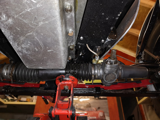
Various solutions have been suggested including a VW steering box however my favoured choice is a Hilman Imp rack from the 1960's. It looked even at an early stage that there was room between the sump and the Bowden assembly for such a modification.
![]() |
| Carboard template of mounting plate for the new steering |
![]() |
| Above plate needed to centralise the rack vs A7 track rods to keep them the same length. |
![]() |
![]() |
| The rack bolted in place with the two plates |
![]() |
| Additional plate to take the new track rod ends |
Two additional plates are required to mate with the front of the Bowden suspension. The first plate centralises the rack vs the track rods (which are the same size) the other function is to make the assembly easier. The second plate has two 80mm standoffs to transfer the action to the front to pick up the track rods.
Conclusion
Friday, 22 March 2019
Volt meter, temp Gauge
I came across this wonderful device from China, it is a 3 functions in one and plugs into a standard cigar lighter 12V socket.
As it turns out I already have a cigar lighter socket (12V outlet) added a couple of years ago to do the Applecross adventure. The temperature sensor is an external thermistor (a resistor that changes impedance with temperature) on a 30mm lead from the unit. If you extend that lead and attach it by araldite to the water system in some way you have a coolant temperature gauge + volt meter that tells you how well the Dynamater is doing and provides a USB connection for charging your phone.
There is one snag I attached the thermistor to the thermostat housing, there is a 25 degree difference between what the thermometer reads and the actual water temperature. so when it reads 55deg C the actual temperature is 80 deg C (the thermostat temperature). When the thermostat closes the water pump runs and maintains a constant temperature in the engine.
![]() |
| Maximum temperature 95deg C |
![]() |
| New thermistor location |
Here is an Index page for the build
Saturday, 9 March 2019
Seat cushions for racing seats
May this be the answer to some longer runs?
Video of recent improvements with Seat Cushions
Here is an Index page for the build
Thursday, 28 February 2019
Dynamator
After taking advice from Ruairidh of Alba Austins in Glasgow I decided to take the plunge, the gears at either end of the Dynamator were fitted from old stock. The reasoning being that only one gear is supplied and of questionable quality.
The conversion is relatively straight forward only the 3 securing bolts, two of which are in a relatively inaccessible place. Great patience is required to remove and reinsert them.
The next part is to attend to the wiring. I found it easier to replace the Lucas Regulator with a 4 way marine terminal block and relabelled the terminals exactly the same as the original regulator. The Yellow wire from the Dynamator (B) can then be shifted to the (A) terminal very easily. The red ignition warning light return (yellow) can then be connected in a similar way to the Dynamator D terminal behind the dash panel (now Green).
My Austin seven wiring has now deviated from the original harness as I have added the following:
* High Torque Starter inc push button start
* Sparkright Distributor with LP dc filter for noise.
* Electric thermostatically controlled water pump
* Headlight dip relay and under dash toggle switch
![]() ![]() |
| Water pump thermostat |
![]() |
| Dynamator |
The results are spectacular, the race battery now copes with all the loads including headlights and water pump. The engine now self regulates the temperature well below boiling point (using a modern cored radiator).
Here is an Index page for the build
Tuesday, 29 January 2019
A7 Tonneau Cover
The truth is I have just ordered a set of custom cushions for the alloy bucket seats so there was nothing left in the budget for a Tonneau, perhaps next year. However I found this cover lying about the workshop, it is a trailer cover but is too small for it so I now have a good use for it.
Update 4th Aug 2021
Here is an Index page for the build
Sunday, 20 January 2019
2017-2019 progress
In 2017 I competed in the Boness Hill Climb and took the car and passenger (Angus) over the Bealach na Ba (P/O West Coast 500, Applecross section).
- Engine rebuild
- New racing gearbox
- Suspension improvements
- Hydralic brakes
- Better exhaust gas flow less bends
- Seat cusions
- New cast iron block
- Light weight racing pistons
- Bespoke con rods
- Phoenix crank
- High lift cams
- Improved oil delivery
- Lightened flywheel
- Racing ratios dog box between 1st and second was obtained via Vintage and Classic workshop
- While the engine was being built I attended to the suspension and brakes
- New brake pedal box with balance bar, dual circuit arrangement
- Twin leading shoe brakes front and single on the rear
- New handbrake leaver
- Reservoir
- Special tooling to install brakes
- New upper wishbones to stabilise suspension at front
- Rear pan-hard rod
- One of the biggest challenges was hacking down the rear diff casting integral brake backplates, with precision, to fit the new cast alloy backplates.
- The brake pedal had to be engineered from scratch.
- The brake pedal mechanism (pedal box) mounting on the chassis had to be fabricated from scratch.
- The handbrake had to be extensively re-engineered.
- The Bowden front suspension had to be extensively reengineered.
Rear diff brake backplates
Brake pedal
Pedal Box
Handbrake
The original site was used for a bobbin pully that reverses the action of the cable the original brake leaver was modified with a clevis to connect to the cable.
Suspension
The suspension was defective on two counts 1) the original Bowden independent suspension did not work well 2) The rear suspension needed a Panhard rod to maintain stability.![]() ![]() |
| Bowden end plate |
The above images show the fabrication of the front suspension the cardboard simulated the mudguard mounting changes. CAD came to the rescue again with a drawing remodeling the Bowden end plates to take the upper wishbone. The drawing was sent to a plasma cutting service. I needed all 4 plates to be made to a tight tolerance.
The rear suspension had a Panhard rod added.
Link to 2019 video
Here is an Index page for the build


